Etch Pits in Heliodor and Green Beryl from the Volyn Pegmatites, Northwest Ukraine: A Diagnostic Feature
ABSTRACT
Green beryl and the yellow beryl variety heliodor are well known from the Volyn pegmatite field in Ukraine, and this study presents details of their morphological characteristics. Visible etch pits are characteristic of beryl from this locality. In addition, they may contain an organic matter called kerite. Formation of the etch pits is associated with a fluorine-rich, late-stage fluid phase. Etch pits on the pinacoidal face have a hexagonal outline and a pointed bottom (originating at linear defects) transitioning to etch pits with very steep walls, and they occur in three different orders of magnitude: ≤500 μm, ≤50 μm, and 1–3 μm. On the first-order prismatic faces, etch pits with a flat bottom (originating from point defects) or pointed bottom are square to rectangular, the latter oriented parallel or perpendicular to the beryl’s c-axis. Flat bottom etch pits are more abundant than pointed bottom and also occur in three different orders of magnitude. In addition, small etch pits with a canoe shape and porosity on the nanometer scale were observed. Scanning electron microscopy of these etch pits was used to distinguish uncut stones from other pegmatitic beryls, but these phenomena are also visible with an optical microscope or even with a loupe.
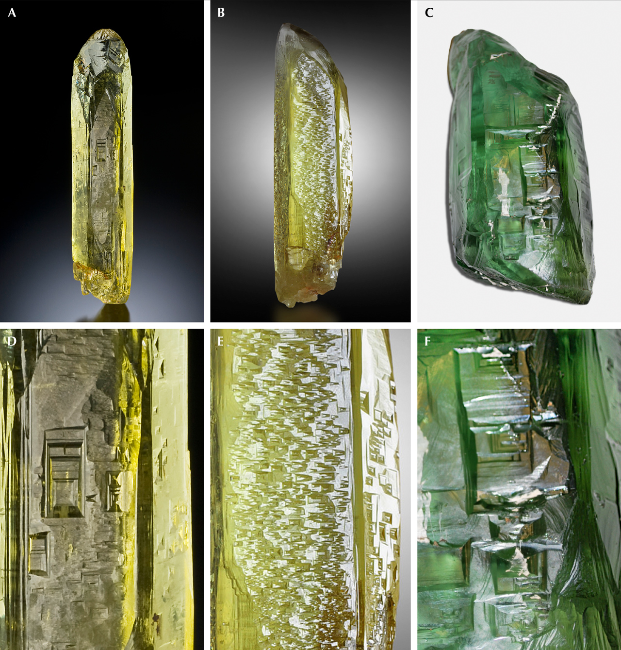
Paleoproterozoic pegmatites near Khoroshiv (formerly Volodarsk-Volynskyi) in northwest Ukraine are known as a source of high-quality green beryl and the yellow beryl variety heliodor (e.g., Koshil et al., 1991; Simmons, 2014, and references therein). The green beryl’s color can be very intense but never reaches the typical emerald color. Aquamarine is also claimed from the Volyn pegmatite field, but very rarely, and emerald from southeast Ukraine (Franz et al., 2020) is the country’s only other important gem beryl occurrence. The finest specimens of Volyn beryl with color between green and yellow (figure 1) and size of up to 140 cm in length are displayed in the Museum of Precious and Decorative Stones in Khoroshiv (Vasylyshyn et al., 2001), while gem-quality crystals up to 55 cm have been sold abroad.
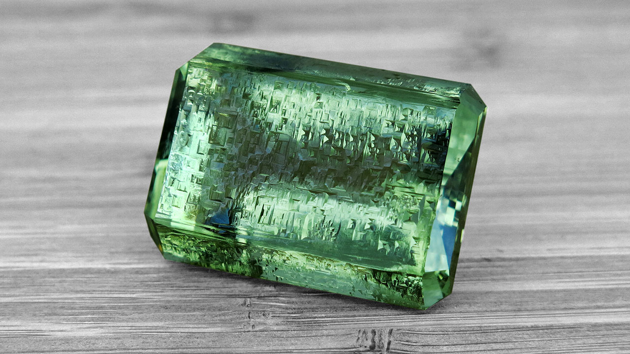
Since 1931, the pegmatites have been mined extensively for piezo quartz, which occurs in exceptionally large crystals from one to two meters (Lyckberg, 2005; Lyckberg et al., 2009, 2019). In addition to beryl, which is present in ~2% of the pegmatites, approximately 10% of these pegmatites contain gem-quality topaz. Among the first gem findings was topaz in 1931–1933, and later gem beryl was recovered as a byproduct. Mining for heliodor continued after World War II, but this material was only available in Eastern Europe. The first crystals reached the Western European market in 1980, and in 1987 Volyn beryl finally emerged at the gem shows in Tucson. Many of these were used for cutting (figure 2), but a large number of fine mineral specimens were also preserved.
Since the early 1990s, the Volyn Quartz Samotsvety Company has conducted mining for beryl and topaz. Lyckberg et al. (2009) reviewed the mining and collecting history, the geology, and the formation of chambers within the pegmatites. That article also contains a list of accompanying minerals in the pegmatite and several photos showing the etch pits.
A characteristic feature of Volyn beryl crystals is their morphology, with exceptionally large dissolution features (etch pits), described on the basis of light microscopy by Bartoshinskiy et al. (1969) and Lazarenko et al. (1973). The prism faces show rectangular cavities with negative crystal faces, while the basal planes show negative, hexagonally shaped crystal faces. Although dissolution of early precipitated minerals during a later stage is frequently observed in pegmatites (Černý, 2002; London, 2008), these features together with the yellow-green color and their size are diagnostic for Volyn beryl. In large crystals, they are visible without magnification, and in smaller crystals they can be seen with the aid of a loupe or optical microscope.
This study presents an investigation of the morphology of the etch pits on prismatic and basal faces in a number of beryl specimens from Volyn by means of scanning electron microscopy (SEM), which helped to identify the origin of uncut stones, extending the work of Kurumathoor and Franz (2018) on etch pits as a provenance indicator. The nomenclature for etch pits follows from that work: F-type = flat bottom, which originate at point defects; P-type = pointed bottom, which originate at linear defects (i.e., edge and screw dislocations); H-type = hollow, with walls almost perpendicular to a face and bottom that is not visible; and C-type = canoe-shaped.
GEOLOGICAL SETTING
The Volyn pegmatites are genetically and spatially connected with granites of the Korosten plutonic complex in the northwest Ukrainian shield. This pluton crops out over an area of approximately 15,000 km2 and has intrusion ages of 1800–1760 Ma (figure 3; Shumlyanskyy et al., 2017, 2021). Its country rocks are high-grade migmatic gneisses. In the Khoroshiv region at its western margin, pegmatites are found in a contact zone between granite and gabbroic rocks over a distance of 22 km and a width of 300 to 1500 m (e.g., Lazarenko et al., 1973; Koshil et al., 1991; Ivanovich and Alekseevich, 2007). Miarolitic cavities, produced during the late-stage crystallization by fluids, occur all along the edges of the pluton. The southern and eastern sides have been test-mined for quartz.

The pegmatites belong to the category of shallow pegmatites, fully differentiated, and are irregularly distributed in the granites (Ivanovich and Alekseevich, 2007). According to the nomenclature of Černý and Ercit (2005) and Linnen et al. (2012), they belong to the miarolitic interior-type of the niobium-, yttrium-, and fluorine-enriched family. They reach a size of several tens of meters; individual pegmatite bodies are typically about 30 m by 40 to 45 m wide (Kalyuzhnyi et al., 1971; Lyckberg, 2005; Ivanovich and Alekseevich, 2007). The pegmatites contain large miarolitic pockets and are referred to in the Ukrainian literature as “chamber pegmatites.” They are zoned around an open cavity, which can reach a volume of approximately 40 m3 and in extreme cases up to 4000 m3 (Lyckberg et al., 2009).
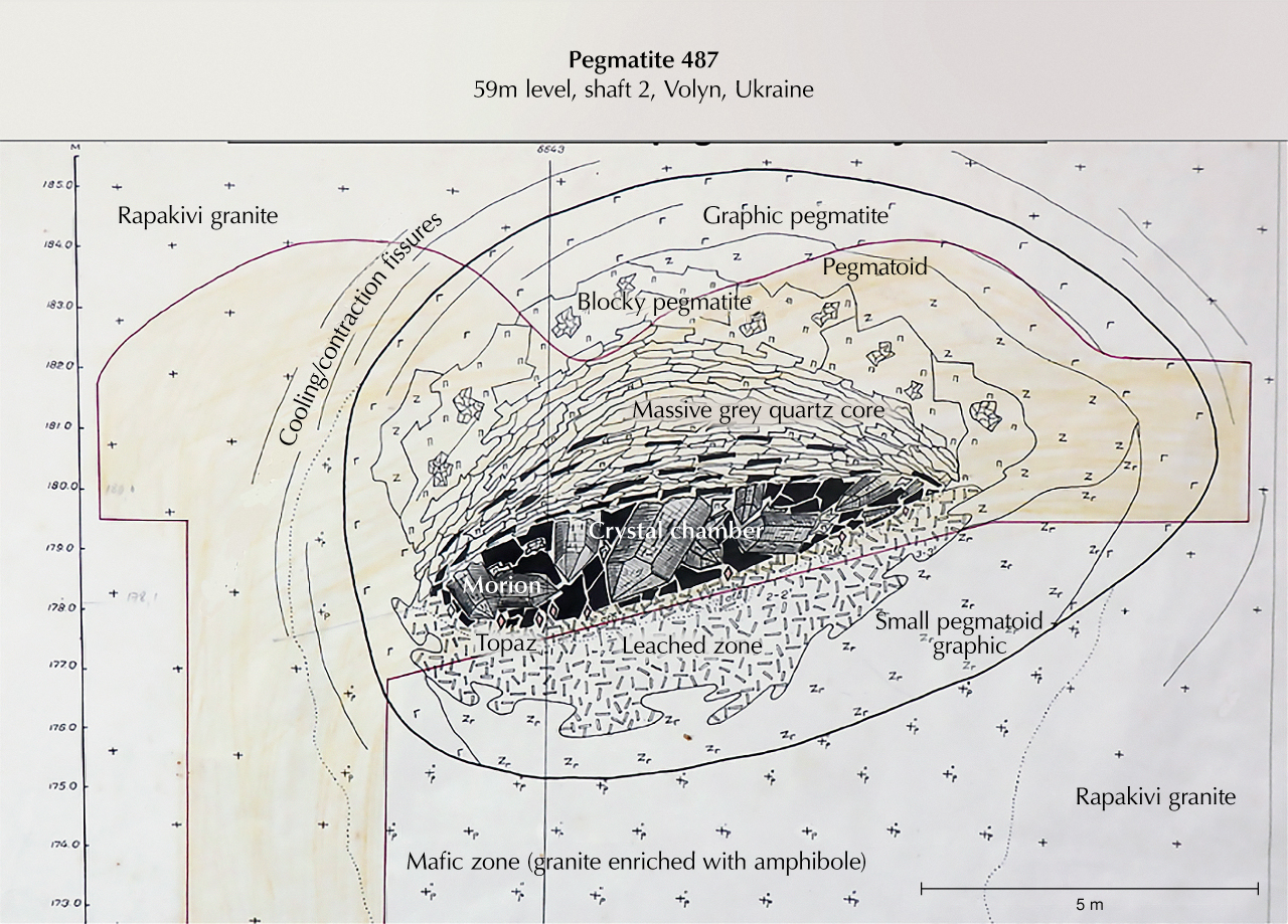
A cross section of a pegmatite is shown in figure 4. Quartz crystals one or two meters in size, most often as smoky quartz, grew from the hanging wall into the chamber. The floor is covered with quartz that has fallen down, as well as smaller crystals of mica, topaz, beryl, and albite. Chambers in which beryl and topaz occur together as large crystals are the exception in these deposits, because during the multistage crystallization conditions they can replace each other. The footwall of the chambers consists of a strongly leached feldspar-rich horizon up to 36 m deep (Lyckberg et al., 2009) where quartz was dissolved, and further down lies a zone of broken-up pegmatite. New mineral formations in this zone include albite, siderite, topaz, fluorite, beryl (rarely), and phenakite. The zones around the chamber are a quartz core above the chamber, then a more or less concentric feldspar zone, a blocky quartz-feldspar zone with large pegmatitic crystals, and next to the granite a zone with graphic-textured quartz-feldspar intergrowths.
Some of the chambers were destroyed forming a breccia, which consists of broken crystals and rock fragments, cemented by quartz, opal, chalcedony, and clay minerals. Pseudomorph replacements of beryl, which now consist of opal, muscovite, bertrandite, buddingtonite, and minor amounts of euclase, albite, potassium feldspar, columbite, pyrite, barite, rare earth element minerals, and organic matter, occur in the breccia (Bartoshinskiy et al., 1969; Franz et al., 2017). The authors recently obtained another sample of a beryl pseudomorph, which contains siderite next to the beryllium minerals bertrandite and euclase, pointing to a variable fluid composition during the latest alteration stages. We also obtained a sample with a pseudomorph of white mica replacing topaz, which again shows the importance of a late alteration stage for the gemstones.
Based on fluid inclusion studies, the pegmatites crystallized at a high fluid pressure, first in a closed system (from 600° to 390°C) and then during cooling in an open system (at 365° ± 15°C) at a depth of 2.0 to 2.5 km (Lukashev, 1976; Kalyuzhnyi et al., 1971; Voznyak, 2007; Voznyak et al., 2012).
Another very special feature of these pegmatites is the occurrence of an organic matter called kerite. It is found within the cavities, attached to feldspar and topaz. It was interpreted as an example of abiogenic (of inorganic origin) formation (Ginzburg et al., 1987; Luk’yanova et al., 1992)—in other words, inorganic synthesis of fibrous carbon hydrates in the cooling stage of the pegmatites. They were later reinterpreted as fossil cyanobacteria (Gorlenko et al., 2000; Zhmur, 2003) from a geyser-type deposit. Recent investigations (Franz et al., 2022, 2023) have also identified a number of different fossils, some of them fungi-like. Filamentous fossils and remnants of former biofilms were also identified in etch pits of beryl.
PREVIOUS WORK ON VOLYN BERYL
Beryl is an accessory mineral found in 2% of the approximately 1500 pegmatite bodies at Volyn. It is present in small amounts in cavity areas, found in clay primarily in the lower sections of the pocket where they once grew on albite (Lyckberg et al., 2009), but their initial location is mostly lost. Beryl crystals are usually sitting in a clay-mica-quartz rock matrix or in a soft clay mass of dominantly kaolinite, as variably oriented individual crystals. Anhedral crystals, measuring no more than 0.5 cm in cross section, also occur in the leached zone under the chamber, where beryl fills cracks and leaching voids in albite.
The Vickers hardness of the Volyn beryl as measured on prismatic faces ranges from 1380 to 1395 kg/mm2 (Lazarenko et al., 1973), corresponding to 7–8 on the Mohs scale. Volyn beryl is characterized by a relatively low density of 2.65 to 2.75 g/cm3 (Gurskyi et al., 2006) and low refractive indices of no = 1.568–1.570 and nε = 1.566–1.567 (Lazarenko et al., 1973).
Only a few chemical analyses of Volyn beryl are available in the literature (Lazarenko et al., 1973; Khomenko et al., 2007; Voznyak et al., 2012). The low contents of sodium (≤0.10 wt.%), lithium (≤0.02 wt.%), cesium (≤0.24 wt.%), iron(II) (≤0.29 wt.%), and magnesium (≤0.03 wt.%), as well as the relatively high Fe3+/Fe2+ ratios (on average near 7:1), are characteristic for Volyn beryl. Titanium, manganese, chromium, vanadium, potassium, calcium, gallium, niobium, molybdenum, and barium were reported as minor elements, mostly below or near 0.01 wt.%.

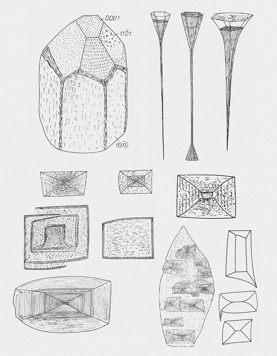
Lazarenko et al. (1973) described different stages of the dissolution of beryl, which produced five morphological types of columnar-prismatic, occasionally spicular beryl crystals (table 1), with characteristically sculptured crystal faces as well as systems of dissolution cones (so-called etch channels). Basal faces are rare. Bartoshinskiy et al. (1969) showed rectangular F- and P-type etch pits with a partly curved outline on the first-order prismatic face and spectacular long, tubular etch pits on the pinacoidal face (figure 5).

The nature of the typical color for Volyn heliodor was studied by Khomenko et al. (2007, 2010) using optical spectroscopy. Variations in the color of Volyn beryl are due to the intensity of the absorption seen in the slope from 28000 to 22000 cm–1 of the strong UV absorption, caused by the O2–-Fe3+ charge transfer in structural or interstitial positions near the cationic vacancies (figure 6). This slope covers the blue absorption at approximately 450–470 nm (22222–21276 cm–1). Fe2+ ions do not affect the color of Volyn heliodors, confirming results of previous spectroscopic investigations by Wood and Nassau (1968), Schmetzer et al. (1975), and Platonov et al. (1984, 2016).
Volyn beryl’s color varies from saturated brownish green to light yellow-green (figures 1 and 2). Most of the gem-quality crystals can be regarded as typical heliodor with a yellowish shade of variable intensity (rare greenish blue crystals are displayed in the Museum of Precious and Decorative Stones; Vasylyshyn et al., 2001). Although some reproductions of crystals from Volyn show an intense green color resembling that of emerald, this is purely a matter of color reproduction: Typical emerald color is not reported from Volyn crystals, in line with the absence of chromium and vanadium. Ukraine’s only emerald occurrence is Kruta Balka (Franz et al., 2020), and the attribution of emerald to Volyn in Grundmann and Giuliani (2002) is probably erroneous. Morganite has not been reported from Ukraine, either.
MATERIALS AND METHODS
For SEM investigation of the etch pits, nine light yellowish green beryl crystals were selected from the collection of the Institute of Geochemistry, Mineralogy and Ore Formation of the National Academy of Sciences of Ukraine (IGMOF NASU) in Kyiv, along with three nearly colorless prismatic crystals (collected by author GF from the mine tailings in 2008) with a partly developed pinacoidal face.
SEM and energy-dispersive X-ray spectroscopy (EDS) were performed using a JEOL JSM-6700F field emission scanning electron microscope equipped with a JED-2300 EDS spectrometer at IGMOF NASU. The spectra were collected with an accelerating voltage of 15 kV and a beam current of 0.65 nA. Operating conditions for each analysis were identical. The samples were cleaned in an ultrasonic bath and then sputtered with a platinum layer of 15 nm thickness. The three nearly colorless crystals were carbon coated and investigated at the Central Facility for Electron Microscopy (ZELMI), Technical University Berlin, using a Hitachi SU8030 cold field emission SEM equipped with an EDAX Octane-A Plus 30 mm2 silicon drift detector for qualitative EDS analysis. Some images were obtained in combination with a backscattered electron (BSE) and SE detector.
Standard gemological properties were investigated on another 16 rough beryl crystals (mineralogical collection of IGMOF NASU) and 20 faceted beryls (private collection of O. Vyshnevskyi) from the Volyn pegmatite field. For refractive index and birefringence measurements, we used an Eickhorst GemLED refractometer. Sartorius CP 224 S analytical lab balances equipped with a hydrostatic attachment were used for specific gravity (YDK01MS Density Determination Kit), using distilled water as fluid. The color of the samples was graded using a GIA GemSet in strong, diffuse daylight.
RESULTS
Gemological Characteristics. The standard gemological properties of the 16 rough and 20 faceted samples are summarized in table 2. All were transparent to translucent, and none showed fluorescence under short- and long-wave UV light. Their refractive indices of 1.568–1.571 (nω) and 1.562–1.566 (nε) and birefringence values of 0.005–0.008 were typical for natural beryl. Samples with stronger yellowish hue showed slightly lower birefringence. Eye-clean rough crystals, as well as all faceted stones, had a specific gravity in the range of 2.66–2.70. Translucent rough beryl had a lower specific gravity range of 2.62–2.65, which may be due to numerous fluid inclusions. Solid inclusions with a size of tens to hundreds of micrometers, brought to the surface in polished sections, were identified by EDS analysis as albite, microcline, muscovite, columbite, iron sulfide, titanium oxide, and iron oxide/hydroxide (possibly goethite).


Morphology of Etch Pits. In general, the “negative faces” of an etch pit follow the symmetry pattern of the crystal. The nomenclature for the description is outlined in figure 7. Faces of the etch pits can be even or stepped; outlines of an etch pit on the crystal face can be straight or curved, symmetrical or asymmetrical.
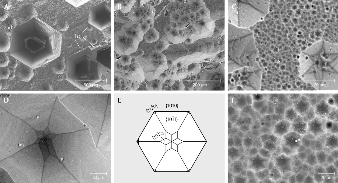
Rectangular etch pits on first-order prismatic faces {1010} and hexagonal etch pits on the basal planes {0001} were formed by dissolution. Pyramidal faces are rarely developed on the investigated crystals. Etch pits on {0001} are P-type; however, some with very steep faces are transitional to H-type (figure 8). We observe three orders of magnitude: First-order etch pits are up to 500 μm in diameter and have a mostly straight hexagonal outline (figure 8A). Second-order etch pits are on the order of 50 μm wide, with a less regular outline, partly overlapping each other (figure 8, B and C). Many of these show at their bottom a star-like pattern (figure 8D), produced by a change from dissolution parallel to the first-order prismatic face {1010} to dissolution parallel to the second-order prismatic face {1121} (figure 8E). The negative crystal produced by dissolution shows the {1010} first-order prismatic face with the {1012} and {1011} first-order hexagonal dipyramidal faces. Third-order etch pits are 1 to 3 μm wide, irregular in outline and very abundant, covering all of {0001} (figure 8, C and F).
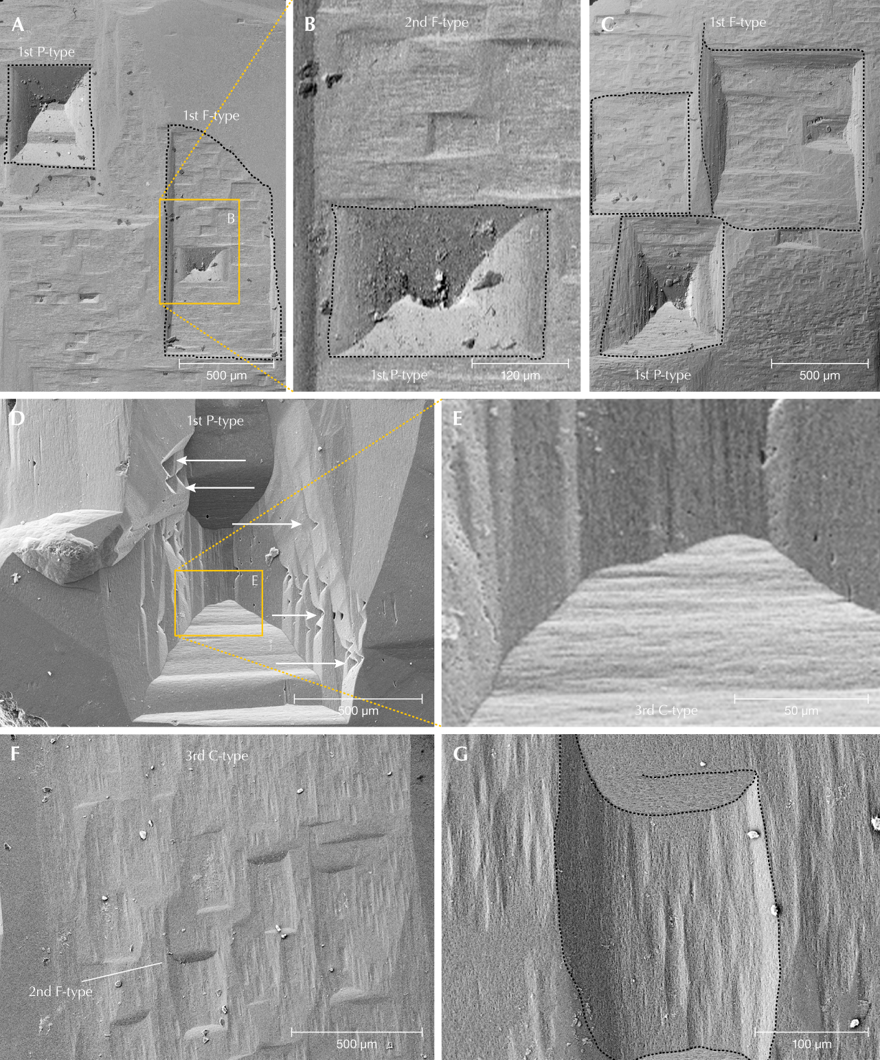
Figure 9 shows etch pits on the first-order prism {1010} of the beryl crystals. These etch pits are rectangular, with their long side parallel to the c-axis (figure 9A), perpendicular (figure 9B), or nearly square (figure 9C). Similar to {0001}, F-type etch pits were observed in three orders of magnitude; however, P-types are much rarer and only observed in first-order, whereas F-types dominate and there is a more or less continuous spectrum for second- and third-order types. In addition, there are small C-type etch pits, which can be oriented perpendicular to the c-axis (figure 9, D and E) or parallel to the c-axis (figure 9, F and G). First-order P-types with stepped sides can be strongly elongated parallel to the c-axis (figure 9, D and E). F-type etch pits show a smooth curvature of the edges (figure 9G), which was also observed in P-types (figure 9B).
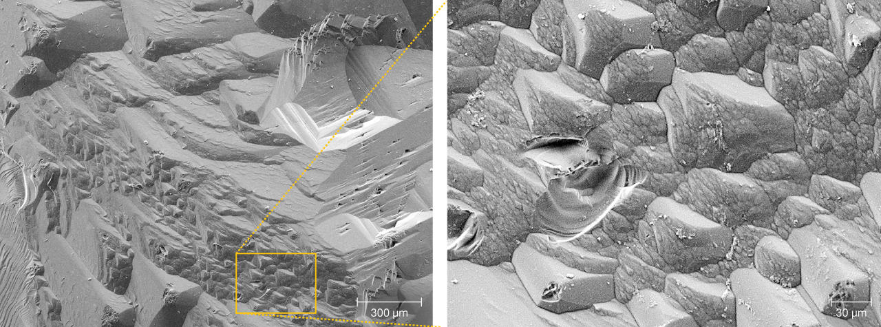
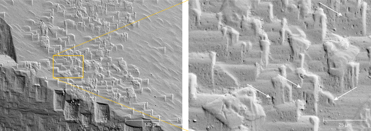
Edges between two first-order prisms are characterized by the presence of triangular hillocks, formed by dissolution of the prismatic faces (figure 1B and figure 10). Pyramidal faces were only observed in one crystal and contained triangular steps (figure 11). On the steps, small third-order F-type etch pits developed.
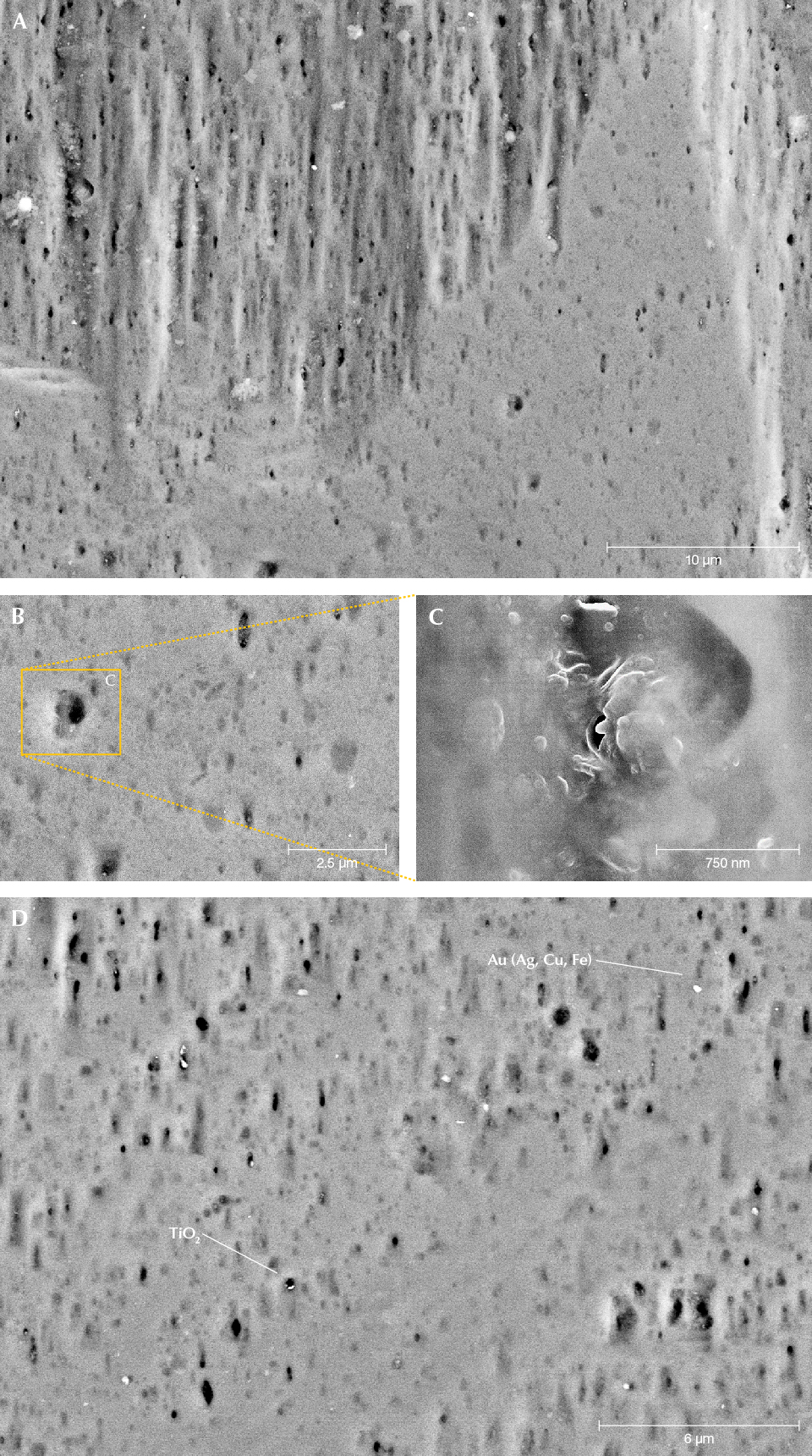
Analysis of the crystals’ surfaces yielded more information about the dissolution process and the components in the dissolving fluid. The faces show a porosity, both outside and inside the etch pits (figure 12) and also within the small C-type etch pits. Individual pores show no crystallographic outline and are on the order of several hundred nanometers, mostly elongated parallel to the c-axis. Very small grains of a titanium dioxide polymorph and gold (with minor contents of silver, copper, and iron as determined by EDS) were observed (figure 12D), as well as particles consisting of a mixture of chloride and sulfate crystals and a particle with light rare earth elements and phosphorous.
DISCUSSION
On a crystal face, the distinction between growth features and dissolution features is based mainly on the observation that growth features, such as growth hillocks, are positive (on the basal plane with a hexagonal shape), rising up on top of each other in stepwise fashion (Sahama, 1966), whereas pits that extend down into the crystal are negative and indicate dissolution. Flamini et al. (1983) showed SEM images of growth features on red (manganese-bearing) beryl from Utah. The features described above on the pinacoid and the prism of Volyn beryl are all interpreted as dissolution features. Phenomena observed at crystal edges and the transition from the prism to the pinacoid are less clear, and we propose that for a provenance study only the pinacoid and the first-order prism should be used.
Dissolution of a mineral can be considered as “negative growth.” As growth is generally described by growth laws (e.g., Philpotts and Ague, 2022), similarly we can describe dissolution by “negative growth laws.” On a crystal face, dissolution is first dominated by the number of defects (i.e., dislocation-controlled). Removal of atoms is energetically favored at defects compared to an ideal surface. At point defects, the defect disappears and removal of atoms produces steps on the crystal’s face in two directions. On a linear defect, the defect extends in the third dimension into the crystal and removal of atoms continues in three dimensions. Once a deep etch pit has formed, dissolution can be rate-determined by diffusion of the components in solution out of the etch pit, and it is then diffusion-controlled. This is what is seen on the pinacoidal face. There are a few first-order etch pits, due to a small number of large screw dislocation bundles, which were formed parallel to the c-axis during growth of the crystal. They can probably extend deep into the crystal as etch channels (Bartoshinskiy et al., 1969).
We interpret the second-order etch pits as due to smaller screw dislocations, which are more frequent (figure 8A) and formed a negative first-order prism. When these etch pits became deep, the dislocation-controlled dissolution was followed by a diffusion-controlled dissolution, and the negative crystal ends with the {1012} and {1011} first-order hexagonal dipyramidal faces. Relative dissolution velocity is—as estimated from the shape and depth of the etch pits—in the sequence of the directions [0001] > [1120] > [1010]. The deep channels (figure 5) shown by Bartoshinskiy et al. (1969) demonstrate that [0001] is a preferred direction for dissolution. Very deep P-type etch pits are also shown in figure 8A, where the bottom is no longer visible. In the diagram in figure 8E, the negative crystal produced by dissolution is shown in the upper part the outline of the {1010} first-order prismatic face with the {1011} hexagonal dipyramidal faces. This indicates faster dissolution in [1120] compared to [1010], leaving traces of the first-order prismatic faces. At the bottom (i.e., with increasing depth), a change is seen from the {1011} first-order hexagonal dipyramidal faces to the {1012} hexagonal dipyramidal faces (figure 8, C and D). This indicates a change in the relative dissolution velocity with increasing depth. Therefore, at the end of the etch pit, the sequence of relative velocities is [0001] > [1010] > [1120], which also implies that dissolution in [1120] is not very different from that in [1010].
Third-order etch pits are very abundant, covering the basal plane completely and also occurring within second-order etch pits (figure 8, C and F). Such a high number of growth dislocations seems unlikely, and we propose that dissolution on these faces is controlled by the crystal structure of beryl with its pronounced channels parallel to the c-axis. Demianets et al. (2006) determined by atomic force microscopy that experimentally produced hydrothermal beryl shows growth hills on the pinacoidal face, with a separation distance of approximately 0.2 μm. The cavities around such growth hills might be correlated with the sites where dissolution is effective in the absence of dislocations, producing the third-order etch pits (figure 8F). The centers of the Si6O18 rings within the beryl structure aligned with the basal planes are sites of preferential removal of atoms, supported by the fact that first-order etch pits are very deep and can extend into the long, funnel-shaped tubes (figure 5; Bartoshinskiy et al., 1969; Lazarenko et al., 1973) perpendicular to the Si6O18 rings. This is also in line with the sodium-poor composition of Volyn beryl. Sodium would be situated within the channels, generally bound to a tetrahedral site with a stronger bond than water and could thus prevent strong dissolution in [0001].
On the first-order prismatic faces, P-type etch pits are rare and most are large, first-order P-types (figure 9), indicating relatively few screw dislocations perpendicular to the c-axis. Prismatic faces are dominated by F-type etch pits, associated with point defects (substituting atoms, vacancies, and interstitial atoms). These etch pits are very abundant, often covering the whole face and overlapping each other (figure 1). They range in size from a centimeter down to several micrometers (figure 9), and though we classified them as first- and second-order etch pits, there is more or less a continuum in size. The outline is rectangular, elongated perpendicular or parallel to the c-axis, or nearly square, indicating essentially equal dissolution velocities in both directions. The sector boundaries are mostly straight, with equal dissolution velocities in both directions, but some show curved boundaries, indicating continuously changing dissolution velocities, also observed in P-type etch pits (figure 9B). First-order etch pits can also be asymmetrical.
Our investigations also yielded some information about the fluid phase, which caused the dissolution. This fluid must have been able to transport elements such as titanium, rare earth elements, and even gold (figure 12D). Furthermore, we know from the locality that in these niobium-, yttrium-, and fluorine-rich pegmatites, fluorine is a major component, as shown by the abundance of topaz as a typical gemstone, by fluorite as an accessory mineral, and by the occurrence of fluorine-rich muscovite (Franz et al., 2017). Beryl and topaz can be related to each other by the chemical equilibrium
Be3Al2Si6O18 + 28 HF ⇌ Al2F2SiO4 + 3 BeF2fluid + 5 SiF4fluid 14 H2O
where beryllium fluoride and silicon fluoride are fluid species. This chemical equilibrium might explain why either beryl or topaz crystallized in the chambers, but rarely both, and it also hints toward a fluorine-rich fluid phase for the late-stage dissolution of the beryl. Lyckberg et al. (2009) noted that when topaz and beryl occur together, one grows at the expense of the other, which supports the interpretation inferred from the chemical equilibrium above.
The large gem-quality crystals with their dissolution phenomena on the surfaces show that possible products of newly formed minerals during incongruent dissolution have been transported away. In other words, we are dealing with an open system. Possible remnants of beryl dissolution as clay-like material are observed in some etch pits, but it is not yet clear whether this material is a product of the dissolution of the beryl or contamination from a late-stage hydrothermal process of other minerals such as feldspar.

The shape and size of the etch pits on Volyn beryl are different from those of other pegmatitic beryls (figure 13; Kurumathoor and Franz, 2018) and may well help to identify uncut crystals. A characteristic feature in particular is that F-type etch pits are much larger (figures 8 and 9) compared to beryl from most other localities. They frequently overlap each other (figures 1, 8, and 9), which is rarely observed in beryl from other localities. The different dissolution stages of the Volyn beryl with varying acidity-alkalinity described in the literature (Barthoshinskiy et al., 1969; Lazarenko et al., 1973) might be correlated with our observation of first-, second-, and third-order etch pits. The degree of etching is quite variable on different crystals, and it even varies from pegmatite to pegmatite (Lyckberg et al., 2009).
The crystal from Minas Gerais in figure 13 shows similarly large F- and P-type etch pits and also small third-order C-type etch pits within F-type etch pits. At Volyn, however, the C-type etch pits are much larger, more abundant, and less regular in outline (figure 13A). C- and P-type etch pits measuring from 5 up to 50 μm, as observed in crystals from Dassu (Himalayas) and China, were not found in Volyn beryl, nor was the orthorhombic outline of F- and P-type etch pits in crystals from Yuno (Himalayas). Aquamarine from Shigar (Himalayas) shows P-type etch pits with a curved outline, which is not observed in the Volyn crystals, but its flat F-type etch pits are similar. Although the geological background of Volyn beryl is most similar to that from Luumäki, Finland (Lahti and Kinnunen, 1993; Lyckberg, 2004), with a similar heliodor color and a similar relation to a Precambrian anorthosite pluton, the etch pits on the prism faces are quite different (figure 13). On the crystals from Luumäki, only P-type etch pits were observed in Kurumathoor and Franz (2018), with an oblique outline and frequent steps. It must be noted, however, that for Kurumathoor and Franz (2018) only a small fragment from one crystal was available, which might not be representative for the occurrence. Furthermore, it must be kept in mind that up to now only a few crystals from the different localities could be investigated using SEM. Future research should be concentrated on more crystals from the same localities and on other beryl varieties with different composition (e.g., rich in sodium-magnesium, lithium-cesium, or manganese) that are also from non-pegmatitic environments.
CONCLUSIONS
Beryl crystals from Volyn are associated with the Korosten pluton in the Precambrian Ukrainian Shield. These crystals are of gem quality, exceptional in size, and have excellent color—both the yellow heliodor and the green beryl. They are found in chambers of pegmatites that formed in the cooling and crystallization stages of the pegmatite melt. A special feature of these beryl crystals is the appearance of dissolution features known as etch pits. On the prismatic face, these etch pits are very pronounced and often cover the whole crystal. On the basal face, they form six-sided channels, ending with pyramidal faces or penetrating deep into the crystal. The shape and size of the etch pits are characteristic for the Volyn occurrence and easily distinguish them from beryl crystals from other localities.